

THERMOELECTRIC COOLERS - INTRODUCTION
Although thermoelectric (TE) phenomena was discovered more than 150 years ago, thermoelectric devices (TE coolers) have only been applied commercially during recent decades. For some time, commercial TECs have been developing in parallel with two mainstream directions of technical progress – electronics and photonics, particularly optoelectronics and laser techniques. Lately, a dramatic increase in the application of TE solutions in optoelectronic devices has been observed, such as diode lasers, superluminescent diodes (SLD), various photodetectors, diode pumped solid state lasers (DPSS), charge-coupled devices (CCDs), focal plane arrays (FPA) and others.
The progress in applications is provided by advantages of TE coolers – they are solid state, have no moving parts and are miniature, highly reliable and flexible in design to meet particular requirements.
HISTORY
The effect of heating or cooling at the junctions of two different conductors exposed to the current was named in a honor of the French watchmaker Jean Peltier (1785–1845) who discovered it in 1834. It was found that if a current passes through the contacts of two dissimilar conductors in a circuit, a temperature differential appears between them. This briefly described phenomenon is the basis of thermoelectricity and is applied actively in the so-called thermoelectric cooling modules. In contrast to the Joule heating, which is proportional to the square of the current:
Q = R x I2
the Peltier heat (Qp) varies as a linear function of the current and changes its sign with it:
Qp = P x q
where q is the charge that passes through the junction (q = I x t); P is the Peltier coefficient, whose value depends on the contacting materials’ nature and the contact temperature. The common way of presenting the Peltier coefficient is the following:
P = α x T
Here, α - alpha is the Seebeck coefficient defined by both contacting materials, properties and their temperature. T is the junction temperature in Kelvins.
Commonly, a thermoelectric module consists of the following parts:
REGULAR MATRIX OF THERMOELECTRIC ELEMENTS – PELLETS
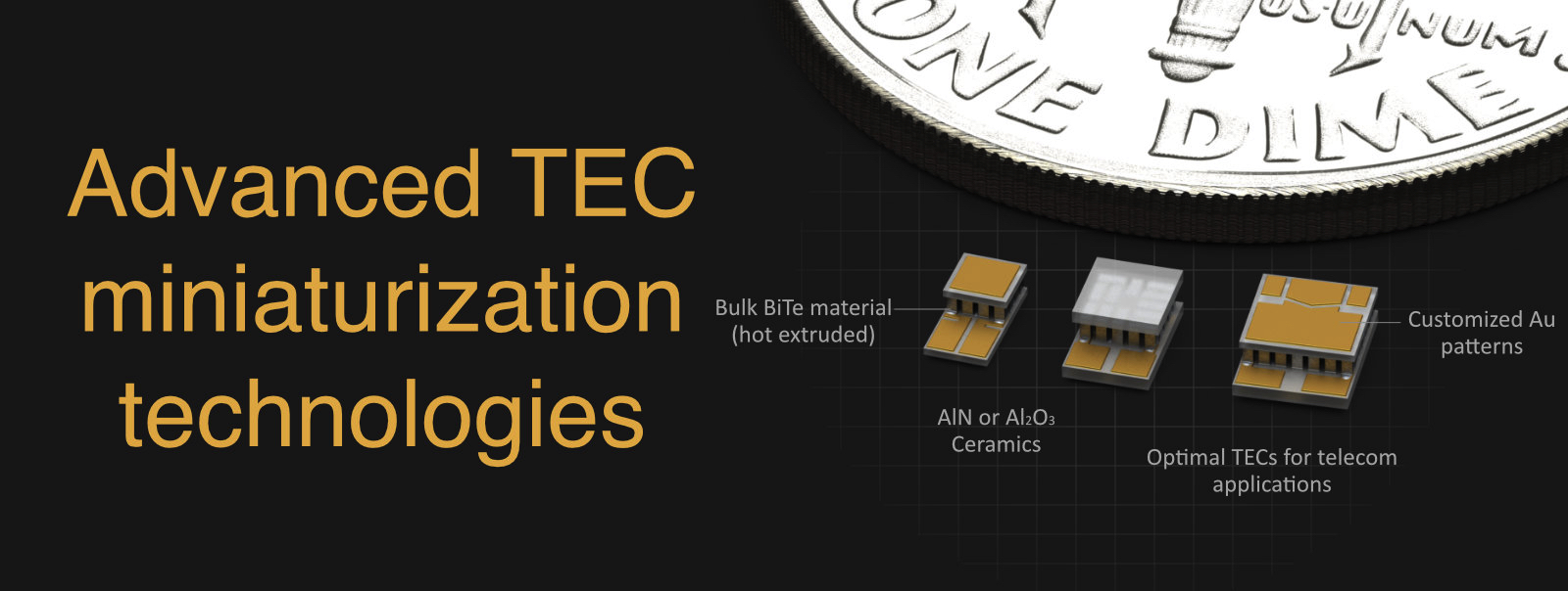
Usually, such semiconductors as bismuth telluride (BiTe), antimony telluride or their solid solutions are used. The semiconductors are the best among the known materials due to a complex optimal TE performance and technological properties. BiTe material is the most typical for TE cooler.
CERAMIC PLATES
– cold and warm (and intermediate for multi-stage coolers) ceramic layers of a module. The plates provide mechanical integrity of a TE module. They must satisfy strict requirements of electrical insulation from an object to be cooled and the heat sink. The plates must have good thermal conductance to provide heat transfer with minimal resistance. The aluminum oxide (Al2O3) ceramics is used most widely due to the optimal cost/performance ratio and developed processing technique. Other ceramics types, such as aluminum nitride (AlN) and beryllium oxide (BeO), are also used. They have much better thermal conductance – five to seven times more than Al2O3 – but both are more expensive. In addition, BeO technology is poisonous.
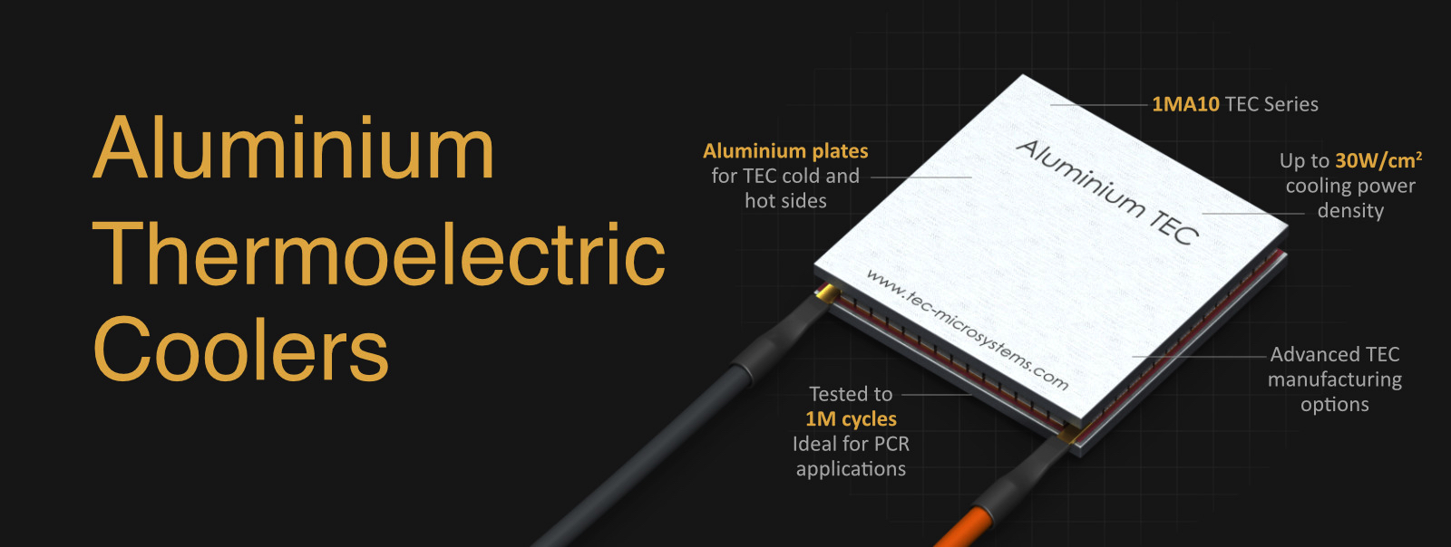
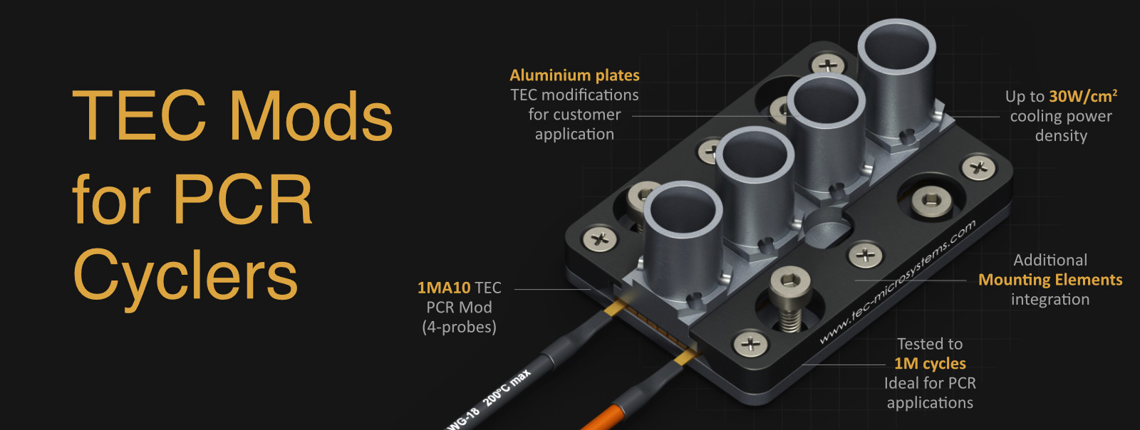
INNOVATIVE SOLUTION - ALUMINIUM PLATES INSTEAD OF CERAMICS
In 2020, TEC Microsystems GmbH introduced an innovative approach to creating thermoelectric modules, replacing traditional ceramics in TEC constructon with aluminum plates. The new 1MA10 TEC Series is a breakthrough in thermoelectric modules for temperature cycling and heavy heatload applications. It enables cycling speeds that are 3-4 times faster, and it demonstrates very high reliability with an average service life that is 4 times longer than traditional ceramic modules have in cycling. The aluminum plates in the TEC design solve one of the main problems in creating reliable thermoelectric systems: matching thermal expansion coefficients with the heat sink. Additionally, using aluminium plates instead of ceramics significantly expands the possibilities for TEC customization. This adds mechanical processing capabilities to plates that are unavailable for ceramic TECs. For instance, threads can be cut into the bottom plate for simple TEC mounting, and the top plate can be shaped as needed using CNC machining.
ELECTRIC CONDUCTORS
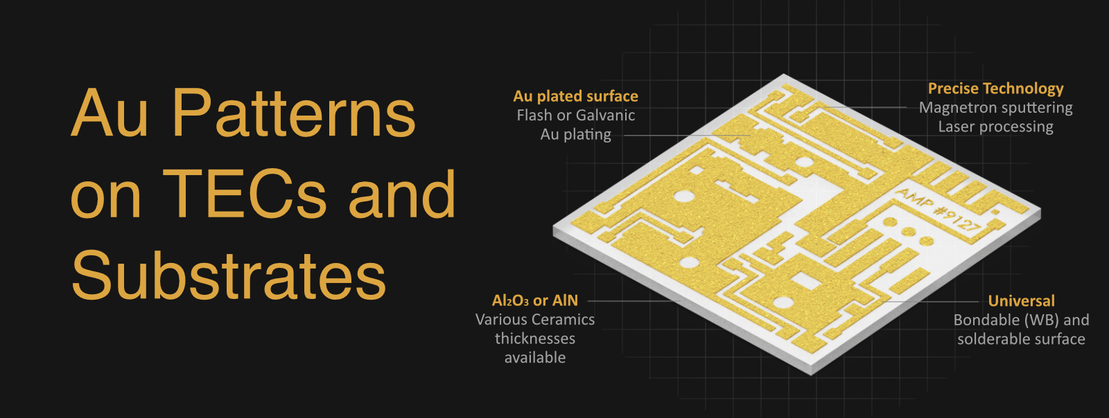
provide serial electric contacting of pellets with each other and contacts to leading wires. For most of the miniature TE coolers, the conductors are made as thin films (multilayer structure containing copper (Cu) as a conductor) deposited onto ceramic plates. For large size, high-power coolers, they are made from Cu tabs to reduce the resistance.
SOLDERS
provide assembling of the TE module. The most standard solders used include Lead-Tin (Pb-Sn), Antimony-Tin (Sn-Sb) and Gold-Tin (Au-Sn) alloys. The solders must provide good assembling of the TE module. The melting point of a solder is the one of limiting factors for TE Cooler reflow processes and operating temperature. Leading wires are connected to the ending conductors and deliver power from a direct current (DC) electrical source.
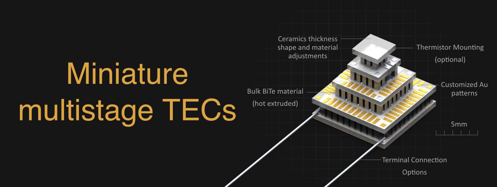
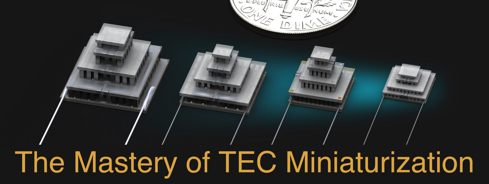
A single-stage module consists of one matrix of pellets and a pair of cold and warm sides. A multi-stage module can be viewed as two or more single stages stacked on top of each other. The construction of a multi-stage module is usually of a pyramidal type – each lower stage is bigger than the upper stage. Once the top stage is used for cooling, the lower stage requires greater cooling capacity to pump heat that is dissipated from the upper stage.
THERMOELECTRIC COOLER PERFORMANCE
Thermoelectric coolers can be characterized by maximal performance parameters with a hot junction temperature (T1). Usually, they are listed in standard specifications of a module:
∆Tmax – maximal Temperature Difference along the module at zero heat load Q=0
Qmax – maximal Cooling Capacity corresponding to ∆Tmax=0
Imax – the device Current at ∆Tmax
Umax – the terminal Voltage for Imax with no heat load
Usually manufacturers specify TE cooler performance parameters at 300K (27ºC) ambient temperature in vacuum or/and at 323K (50ºC) in dry Nitrogen (N2) conditions.
All of the performance parameters are in an interdependent relationship with each other. The correct analysis of a TEC operation in the real application could be carried out using performance plots, which are the results of the interdependence between them. It is important to note that TE cooler performance parameters depend on ambient conditions.
THERMOELECTRIC COOLERS - STANDARD PERFORMANCE PLOTS
A typical specification for thermoelectric cooler contains performance plots, that indicate the inter- dependent relationship between Imax, Umax, Qmax and ∆Tmax. The typical examples are shown in example above. Usually TEC performance parameters and standard performance plots are specified by manufacturers at 300K, vacuum ambient conditions and at 323K, dry N2.
TEC FIGURE-OF-MERIT (Z)
There are more performance parameters that are usually not presented in standard specifications of commercial TE coolers, but that play a very important role in a thermoelectric module characterization.
These parameters are the properties of pellet material (thermal conductance (k), electrical resistance (R) and the Seebeck coefficient) combined as follows:
TEC RELIABILITY
Commercial TE coolers provide long operation lifetime in the range of 250,000 to 350,000 hours at normal conditions. It is the result of a highly developed technology of manufacturing and high-quality raw materials. In many applications, TEC is a critical component because it affects the temperature of the whole device and can have an influence on its correct operation, as well as an impact on heat dissipation. That is why severe reliability test procedures are required.
SELECTION OF TE MODULE FOR AN APPLICATION
Every specific application where a TE module is required is characterized by a set of operation parameters and restrictions, which dictate the necessity of accurate selection of the optimal TEC type among a wide range of single and multi-stage TECs. These parameters are:
∆T – operating temperature difference (at known ambient Ta/hot junction Th temperatures);
Q – operating cooling capacity;
I – applied or available current;
U – terminal voltage; and dimensional restrictions and others.
A user can make a rough but fast estimation of cooling capacity as:
Among each group (single and multi-stage types), there are modules with different cooling capacity Q. Thermoelectric cooler cooling capacity depend on the number of pellets and their geometry. Low height pellets or/and larger pellets cross-section provide higher cooling capacity value for thermoelectric cooler. In the same time they increase the operating current and total power consumption. Small pellets cross-section and tall pellets increase maximum temperature difference and reduce TEC power consumption, but cooling capacity is reduced too.
If also considering the usual restrictions in the power supply, the correct selection can become rather a complicated task. In order to accelerate and optimize this procedure, most of the suppliers advise a kind of assistance. In addition, some of them advise users about software that allows them to search among TECs and decide on the optimal choice using computer database analysis of existing TE module types with detailed modeling of a concrete TE module behavior in particular operating conditions. TEC Microsystems can provide all necessary estimations upon request.
THERMOELECTRIC COOLER MOUNTING
In practice, the performance and operational lifetime of thermoelectric cooler depends considerably on many factors, and proper mounting method is the very important one. Mounting is the first procedure before any application of a TE cooler. The mounting method and applied materials must provide good thermal contacts and minimum heat resistance.
MECHANICAL MOUNTING
TE module is placed between two heat exchangers. This sandwich is fixed by screws or in another mechanical way. The advantage of fixing by screws lies in the possibility to make a fast and easy disassembling if required. It is suitable for large coolers, for example, with external surfaces measuring 30 x 30mm2 or more. Miniature types require different assembling methods.
SOLDERING
This is a universal method for most of the miniature TE coolers. This method involves preparation of the TE module with metal-covered outside surfaces (cold and warm sides). During soldering, a TE cooler is heated for a short time, but up to a high temperature. Therefore:
- the melting point of the outside solder must always be lower than the internal solder of the module; and
- soldering duration needs to be as short as possible to reduce the overheating time.
Usually, it is not recommended to apply soldering for TECs with linear dimensions of sides measuring more than 18mm because of thermal stress. In this case a very careful materials choice is required.
GLUING
is used widely due to simplicity. Usually, epoxy compounds filled with thermoconductive material, such as graphite powder, silver, silicon nitride (SiN) and others, are used.
However, there are general restrictions as follows.
- Some epoxies have low operation temperatures, making them unsuitable for high-temperature TE coolers.
- It is not a proper method for high-vacuum applications because epoxy involves problems with outgassing.
Materials and References:
1. G. Gromov, GLOBAL PHOTONICS APPLICATIONS & TECHNOLOGY Report
2. L. I. Anatychuk, Thermoelements and Thermoelectrical Devices, p.151, Kiev, 1979.
3. A. L. Vayner, Thermoelectric Coolers, Moscow, 1983, pp. 30–35.
4. L. G. Stokholm, “Reliability of thermoelectric cooling systems”, Proceedings of Xth International Conference on Thermoelectrics, Cardiff, UK, 1991, p. 228.
5. H. H. Woodbury, L M Levinson and R S Lewandowski, “Z-Meters”, CRC Handbook of Thermoelectrics, CRC Press, Inc., 1995, pp. 181–189.
6. A. F. Ioffe, Semiconductor Materials, Moscow, 1960.
7. L. S. Stilbans, Semiconductor Thermocoolers, Leningrad, 1967.
8. G. N. Dulnev, Thermal Exchange in the Radioelectrical Devices, Leningrad, 1963.
Images and illustrations by Tim Gromov, TEC Microsystems GmbH
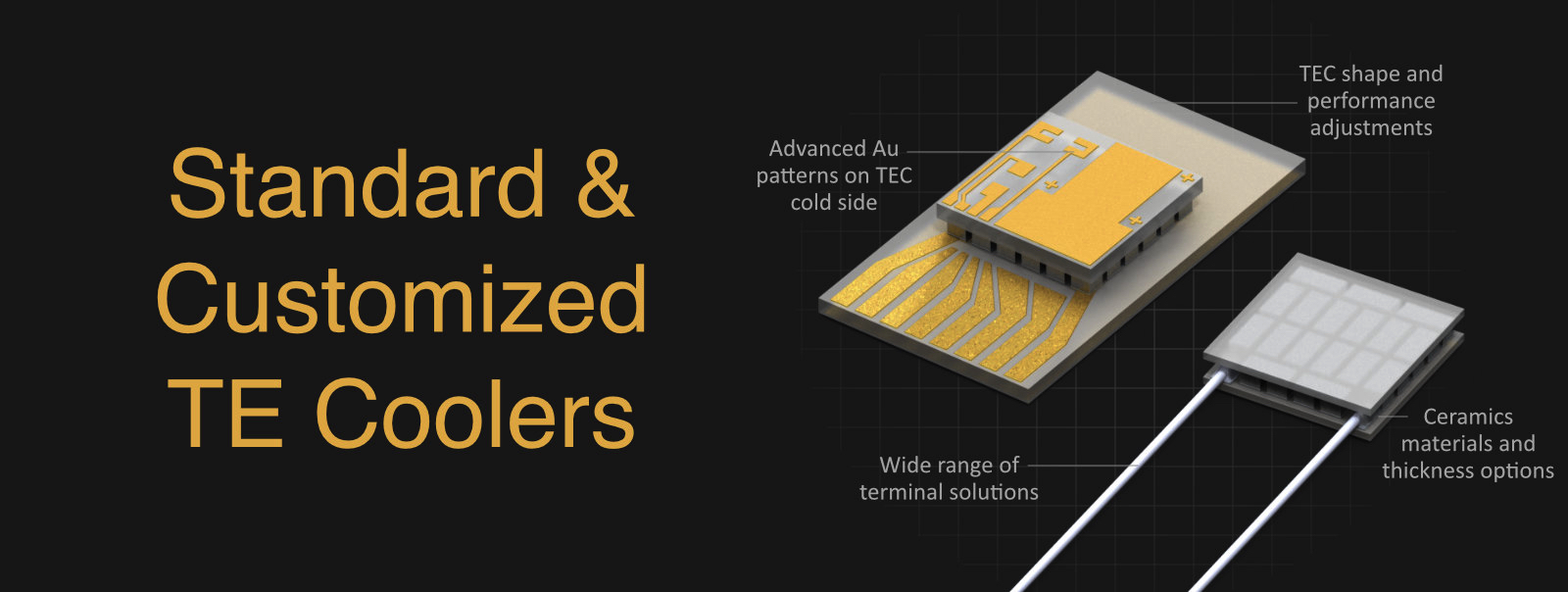
THERMOELECTRIC MODULE CONSTRUCTION
A TE module is a device composed of thermoelectric couples (N and P-type semiconductor pellets) that are connected electrically in series, in parallel thermally and, fixed by soldering, sandwiched between two ceramic plates. The latter form the hot and cold thermoelectric cooler (TEC) sides. The configuration of classical thermoelectric coolers is shown below:


The parameter Z is usually referred to as “figure-of- merit”. The typical value of Z in 2.5 - 3.2 x10⁻³K-1 range. The known value of Z allows estimating of ∆Tmax of a single-stage TEC by the simple formula:
where T0 is the sold side temperature.


RELIABILITY TEST STANDARDS.
For these purposes, there are many national and international test standards. They are unified for a range of electronic and optoelectronic device qualifications. In the international market, Bellcore standards are the most common, namely, GR–468 (Reliability Assurance for Optoelectronic Devices).
The minimal standard set of the test methods contains mechanical shock test, the vibration test, shear force test, the high-temperature storage test, the temperature cycle endurance test.
FAILURE CRITERIA. The suggested failure criteria that are in practice for reliability tests are the following:
- drop in TEC maximum cooling capacity ∆Tmax of below its specified rating
- and an increase in TEC resistance of 5% or higher.
Controlling both the criteria is achievable in the method of Z-metering, which is fast and quite accurate, realized by the test device Z-Meter. The latter provides the measurement of the figure-of- merit Z and therefore the ∆Tmax and alternating current resistance (AC R) measurement.
Parameters Z and ACR are extremely sensitive to the TEC quality and to any failure. Any slight changes in a module – destruction of pellets, junctions, ceramics and so on – immediately result in the noticeable change of Z (decrease) and ACR (raise) against initial fixed values.


Email: info(at)tec-microsystems.com
Phone: +49 (030) 6789 3314
Fax: +49 (030) 6789 3315


